2023 - Volume #47, Issue #2, Page #40
[ Sample Stories From This Issue | List of All Stories In This Issue | Print this story
| Read this issue]
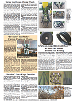
Cub Dozer Tracks Driven Independently
 |
 |

Most older crawler vehicles had an open differential with drive sprockets on each side and independent brakes to turn the vehicle, says Smith. I wanted two tracks independently driven, so one could run forward while the other reversed at the same time.
Smith wanted to emulate modern tracked equipment with hydraulic final drives. However, he wanted to do it with Cub transmissions. He also recognized that garden tractor brakes are not robust enough to handle differential braking. His solution was to design a dozer with two hydrostatic transmissions, one at the front and the other at the rear of the machine.
Once he had his drive system planned out, Smith prepared his Cub. This included extending the frame and beefing it up. He also needed drive axles front and rear.
I used the frames and rear ends from two Cubs to make a dozer frame that was about 2 ft. longer than an original with a drive axle and differential at each end, says Smith. I used about 2/3 of the original frames, welding them together in the middle. I also used all of the original housing.
He laid 2 by 4s on top of the frame to add structural support for the blade, hood and power system, as well as to raise the seat. He also mounted 2 by 4-in. cross members under the original Cub frame to carry bogey wheels and a series of rollers to support the weight of the tractor on the tracks.
Most of the framing was designed on the fly, says Smith. I had very little in the way of plans. If something didnt work, Id cut it off and try something else. Thats all part of the fun.
With the framing, drive axles and differentials with transmissions in place, he used 3/4-in. round stock for a shaft to connect the two transmissions.
The Cub only puts out 14 hp., says Smith. At 3,600 rpms, there isnt that much torque.
To get power to drive the shaft, Smith mounted the front 2/3 of another Cub, less the front axle, on top of the extended and raised frame. This included the engine, radiator, grill, hood, fuel and water pumps, etc., essentially the power system for the dozer and the original frame it sat on.
I used a twin belt pulley from the engine to a double pulley on the shaft between the transmissions, says Smith. The next challenge was building levers and linkage to operate the transmissions and get it all inside the frame. That took some finagling.
He knew the movement of linkage in a Cub hydrostatic was only about 2 1/2 in. from forward to reverse. He sized the linkage arms and put multiple holes in them so he could adjust the throw/sensitivity.
I ended up moving to a less sensitive hole as I tested them out, basically copying the way they operate in a standard Cub, says Smith.
He then went to work to modify the differential. He mounted a drive sprocket on the right side of the front axle and disconnected the left side to freewheel.
At the rear end, he reversed the procedure. He mounted a drive sprocket on the left side and left the right side freewheeling.
The dual systems allow me to run one track in forward gear while the other is running in reverse, says Smith.
The 15-in. sprockets had been purchased, but mounting them to the Cub wheel hub required some machining. He had to drill holes to match the five-lug bolt circle.
Theres a formula you can find online that tells you how to move the mill to drill the holes, says Smith. I had to repeat the milling process on the other sprockets and idlers. I bought spacers to move the tracks out a specific amount. If theyre too close, they wont turn well. I also needed legroom.
Before starting on the dozer, Smith had acquired a Langmuir CNC table and a plasma cutter. He also upgraded his air compressor and installed an air-drying system to prevent steam erosion of the nozzle on the plasma cutter. He estimates the total costs ran around $8,000, but he put it to good use on the dozer, especially as he added the track system.
I used Fusion 360 Auto Cad to design parts and cut them out on the table, says Smith. There was a learning curve to using it, but the software to run the Langmuir CNC table was easy to use.
The tracks revolve around 4 by 6 steel tubing. With both ends of the dozer being used for drive, he couldnt simply telescope the front end for chain mounting and removal. Instead, he used the CNC to cut out two idler wheels and mounted them like the high-wheel drive sprockets found on modern dozers.
I made them like giant pulleys so the chain would ride in the groove, says Smith. They have a 3-pt. top link to tension them. When released, they pivot forward and down to release the track.
To make the track, Smith bought heavy-duty 2 1/2-in. chain. With the aid of the CNC table, he cut out steel pads that he welded to the chain.
Each track uses about 14 ft. of chain, says Smith.
With the tracks and their drive system in place, Smith turned to the front of the dozer. He adapted a Land Pride, 3-pt. scraper blade for use as a front-end blade. He mounted it to what is essentially a CAT 1 3-pt. hitch. Hydraulic cylinders attached to vertical steel plates lift and lower the blade.
I needed something to support the cylinders that would raise and lower the blade, says Smith. On a real dozer, the cylinders would connect to the sides of the hood, which would have been structural. However, there is nothing like that on a garden tractor.
The vertical plates bolt to the original frame and the subframe. Cross supports give them added strength and serve as mounts for other cylinders that adjust blade angles. Lift cylinders can be operated individually to tilt the blade for crowning a road or driveway. A second cylinder angles the blade, while a third changes the pitch so the cutting edge digs in more.
I use a charge pump on the rear hydrostatic. It was used to raise and lower its former mower deck, says Smith. It operates at only 600 psi with 1 to 2 gals. of flow, says Smith. However, its plenty, as I dont need a fast response on the hydraulics.
Smith reports the dozer is working fine. He only made one change after noting the hubs moved 1/16 in. or so when operating under load. He suspected it was due to the spacers. Although he was comfortable that the axles wouldnt break, he was concerned about fatigue if they flexed consistently.
I added outboard brace plates with bearings to support the bearings on the axles, says Smith. Theyre bolted to the 4 by 6 track frames and prevent the spindles from flexing too much. It was just a little added safety.
Contact: FARM SHOW Followup, Hartley Frank Smith (woodandmetalshoptime@gmail.com).
Click here to download page story appeared in.
Click here to read entire issue